Key Features
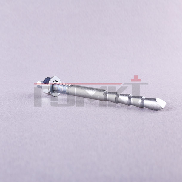
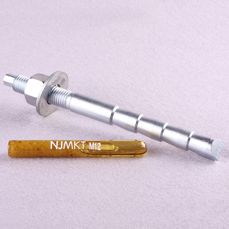
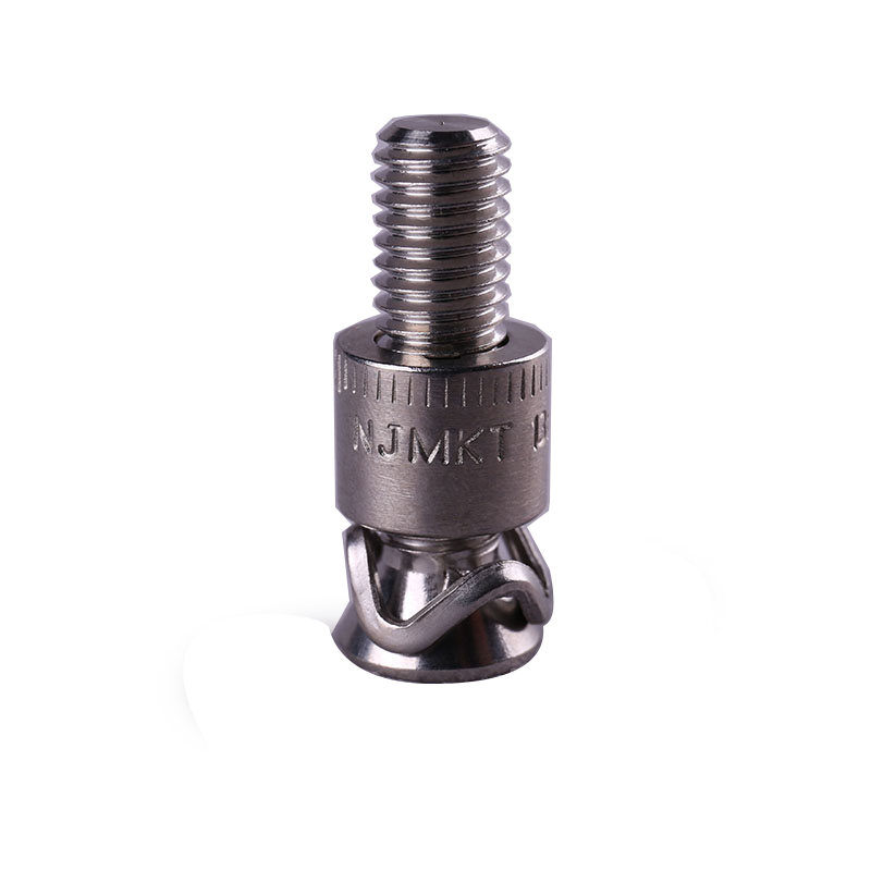
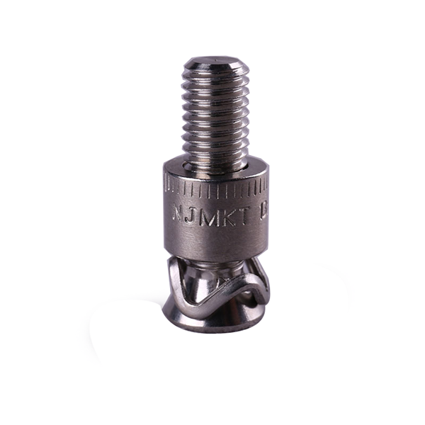
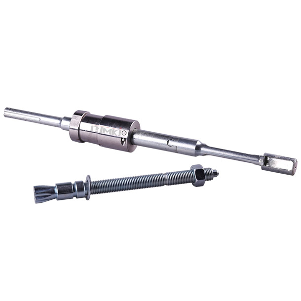
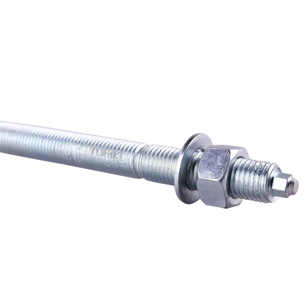
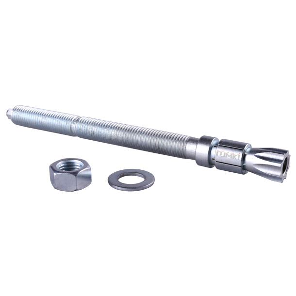
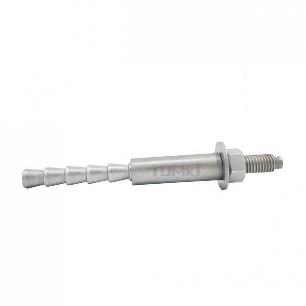
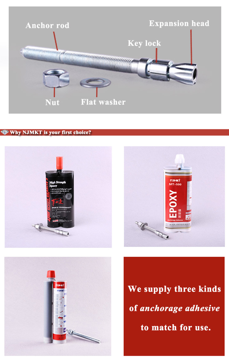
● Consist: anchor rod, key lock, expansion head, washer, nut
● Material:carbon steel, alloy steel, stainless steel
● Grade: grade 5.8, 6.8, 8.8, 10.9, 12.9
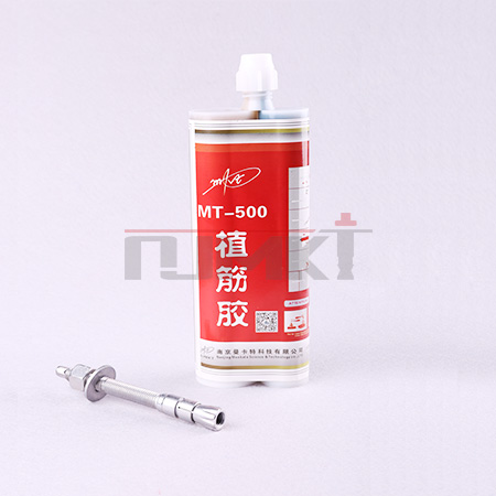
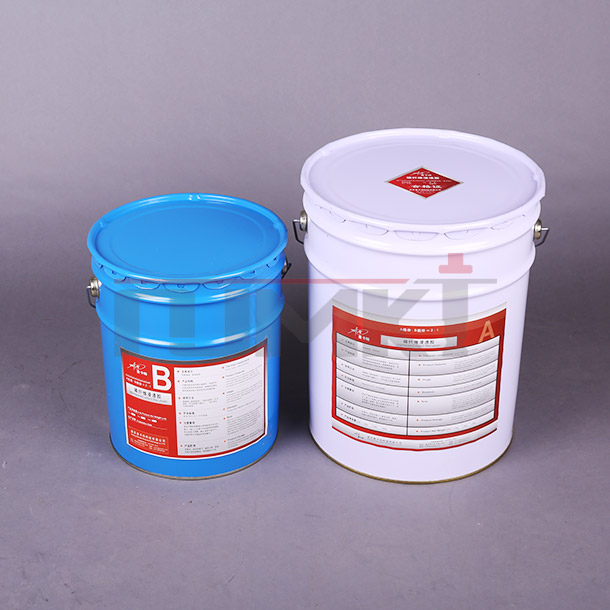
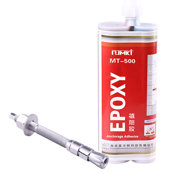
● Adhesive:standard-equipped with our MT-500 Anchorage Adhesive, modified epoxy resin, high temperature resistance and aging resistance for 50 years.
Characteristics
● The wall of drilled hole and mechanical key lock forming the keying effect and providing superior load-carrying capacity to finish the anchorage
● High load-bearing capacity, not only features the advantages of mechanical anchors, but also combines with the seismic resistance and impact resistance of bonding adhesive
● Strong anchorage bonding strength achieves the effect of embedded parts
● Free of phenylethene and ethylenediamine, nearly odorless, non-toxic
● Simple operation, fast and easy dispensing by mixing nozzle ensures accurate mixing proportion
● Cap design is available for several times to use the total amount of adhesive
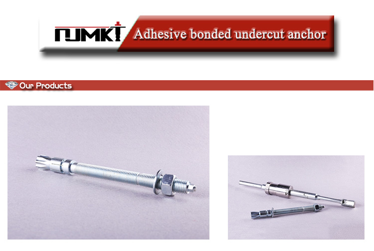
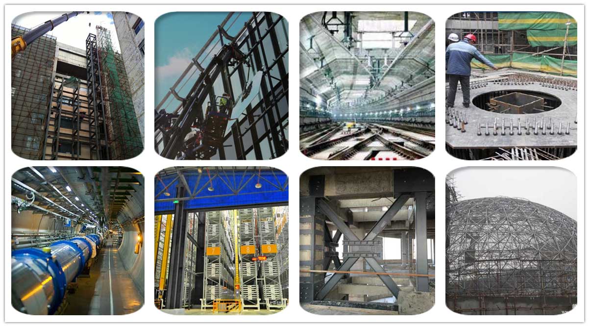
● Connections and installation for all kinds of curtain wall and steel-work constructions
● Connections and installation for large-scale equipment such as industrial plant, crane, conveying system, etc.
● Baffle plate, hanging plate, acoustical plate, security gates and windows fixing
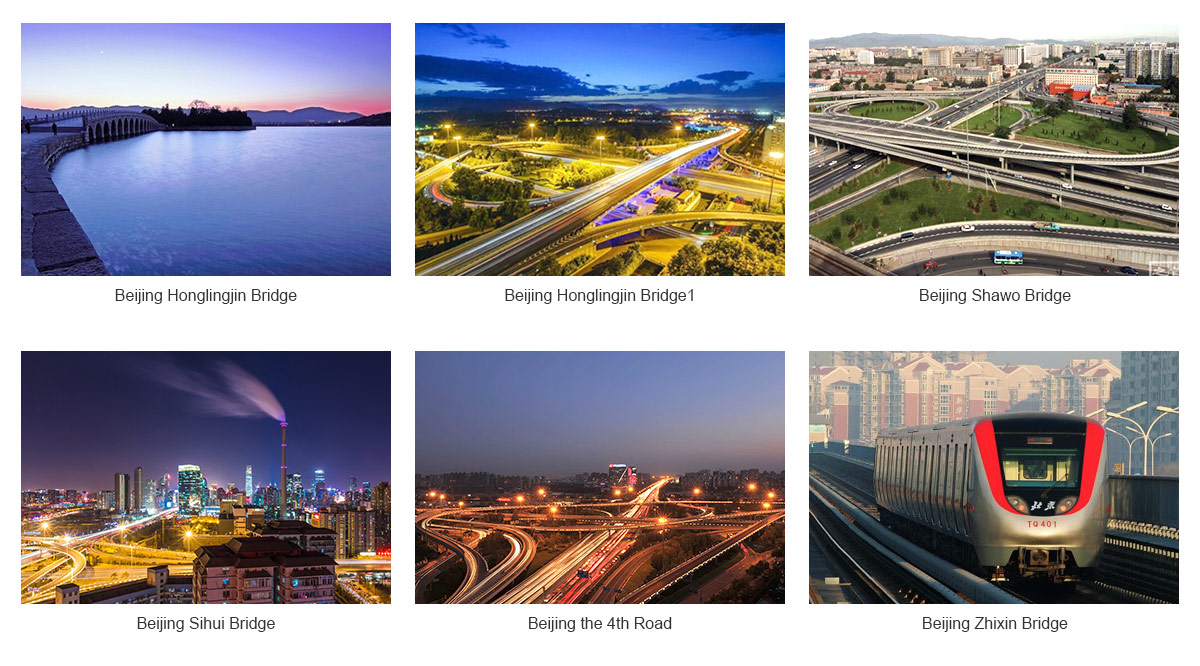
● Widely used for various pipeline and cable bracket installation in bridge, railway track, subway engineering construction, etc.
● Suitable for the highest safety requirement of concrete anchorage, seismic resistance and impact resistance
Installation flow chart
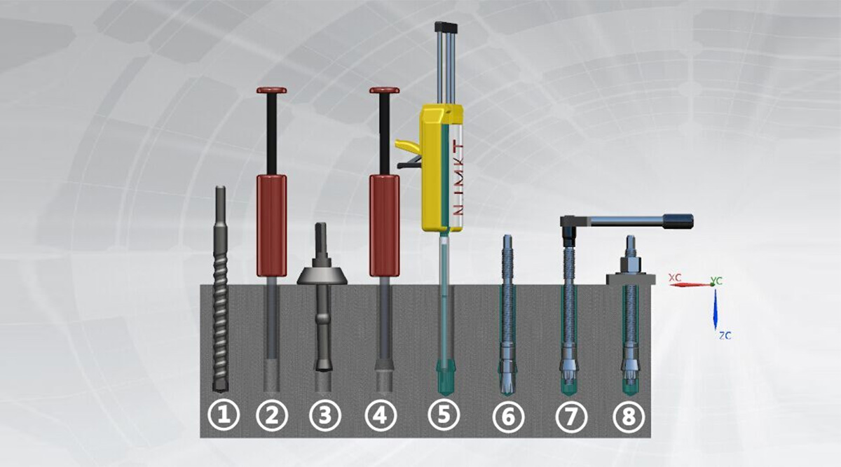
1.Hole drilling
2.Hole cleaning using brush
3.Secondary drilling
4.Hole cleaning using compressed air
5.Adhesive injection
6.Embed the anchor
7.Adjust torque wrench
8.Installation finish
| Size | Texture/Grade | Effective embedment depth hef [mm] | Standard tensile strength/design value | Standard shear strength/design value | Drilled hole dia. | Maximum anchorage thickness | Mounting torque | Concrete cone failure | Concrete splitting failure | total length of screw | ||||||
| cracked | uncracked | cracked | uncracked | critical intervals | Critical margin | minimum spacing | minimum margin | critical intervals | Critical margin | |||||||
| M8 | 5.8 | 80 | 18.3*/12.2 | 18.3*/12.2 | 7.3/6.1 | 7.3/6.1 | 12 | 16 | 12 | 240 | 120 | 80 | 80 | 240 | 120 | 110 |
| 8.8 | 25.1/13.9 | 29.3*/19.5 | 11.7/9.7 | 11.7/9.7 | ||||||||||||
| 304 | 18.3*/6.4 | 18.3*/6.4 | 3.8/3.2 | 3.8/3.2 | ||||||||||||
| 316 | 25.1/13.4 | 25.6*/13.7 | 8.3/6.9 | 8.3/6.9 | ||||||||||||
| M10 | 5.8 | 90 | 29.0*/19.3 | 29.0*/19.3 | 11.6/9.7 | 11.6/9.7 | 14 | 22 | 20 | 270 | 135 | 90 | 90 | 270 | 135 | 130 |
| 8.8 | 29.8/19.9 | 41.8/23.2 | 18.6/15.5 | 18.6/15.5 | ||||||||||||
| 304 | 29.0*/10.2 | 29.0*/10.2 | 6.1/5.1 | 6.1/5.1 | ||||||||||||
| 316 | 29.8/16.5 | 40.6*/21.7 | 13.1/10.9 | 13.1/10.9 | ||||||||||||
| M12 | 5.8 | 110 | 40.4/22.4 | 42.2*/28.1 | 16.9/14.1 | 16.9/14.1 | 16.5 | 24.5 | 40 | 330 | 165 | 110 | 110 | 330 | 165 | 160 |
| 8.8 | 40.4/22.4 | 56.5/31.4 | 27.0/22.5 | 27.0/22.5 | ||||||||||||
| 304 | 40.4/13.4 | 42.2*/14.8 | 8.9/7.4 | 8.9/7.4 | ||||||||||||
| 316 | 40.4/20.9 | 56.5/31.6 | 19.0/15.8 | 19.0/15.8 | ||||||||||||
| M16 | 5.8 | 125 | 48.9/27.2 | 68.5/38.0 | 31.4/26.1 | 31.4/26.1 | 22 | 31 | 60 | 375 | 190 | 125 | 125 | 375 | 190 | 190 |
| 8.8 | 48.9/27.2 | 68.5/38.0 | 50.2/41.9 | 50.2/41.9 | ||||||||||||
| 304 | 48.9/19.8 | 68.5/27.5 | 16.5/13.7 | 16.5/13.7 | ||||||||||||
| 316 | 48.9/27.2 | 68.5/38.0 | 35.4/29.5 | 35.4/29.5 | ||||||||||||
| M20 | 5.8 | 170 | 77.6/43.1 | 108.6/60.3 | 49.0/40.8 | 49.0/40.8 | 25 | 57.5 | 100 | 510 | 255 | 170 | 170 | 510 | 255 | 260 |
| 8.8 | 77.6/43.1 | 108.6/60.3 | 78.4/65.3 | 78.4/65.3 | ||||||||||||
| 304 | 77.6/27.5 | 108.6/42.9 | 25.7/21.4 | 25.7/21.4 | ||||||||||||
| 316 | 77.6/43.1 | 108.6/60.3 | 55.1/45.9 | 55.1/45.9 | ||||||||||||
| M24 | 5.8 | 210 | 106.5/59.1 | 149.1/82.8 | 70.6/58.8 | 70.6/58.8 | 28 | 53 | 160 | 630 | 315 | 210 | 210 | 630 | 315 | 300 |
| 8.8 | 106.5/59.1 | 149.1/82.8 | 112.9/94.1 | 112.9/94.1 | ||||||||||||
| 304 | 106.5/37.2 | 149.1/52.2 | 37.1/30.9 | 37.1/30.9 | ||||||||||||
| 316 | 106.5/57.1 | 149.1/79.9 | 79.4/66.2 | 79.4/66.2 | ||||||||||||
| M27 | 5.8 | 250 | 138.3/76.8 | 193.7/107.6 | 91.8/76.5 | 91.8/76.5 | 32 | 63 | 200 | 750 | 375 | 250 | 250 | 750 | 375 | 350 |
| 8.8 | 138.3/76.8 | 193.7/107.6 | 147.2/112.6 | 147.2/112.6 | ||||||||||||
| 304 | 138.3/48.4 | 193.6/67.7 | 48.2/40.2 | 48.2/40.2 | ||||||||||||
| 316 | ———— | ———— | ———— | ———— | ||||||||||||
| M30 | 5.8 | 280 | 163.9/91.1 | 229.5/127.5 | 112.2/93.5 | 112.2/93.5 | 35 | 59 | 240 | 840 | 420 | 280 | 280 | 840 | 420 | 380 |
| 8.8 | 163.9/91.1 | 229.5/127.5 | 179.5/149.6 | 179.5/149.6 | ||||||||||||
| 304 | 163.9/57.3 | 229.5/80.3 | 58.9/49.1 | 58.9/49.1 | ||||||||||||
| 316 | ———— | ———— | ———— | ———— | ||||||||||||
● The values are suitable for: correct installation, no influence of spacing and edge distance, minimum base material thickness.
● All the data applies in C20/25 concrete base material. If the base material grade changes, the corresponding concrete influence coefficient will needs to be increased.
● The * part in the table is steel failure control.
● Design load: including material partial factor, but not including overall partial factor.
● Recommended load: including not only material partial factor, but also including overall partial factor 1.4.
● If your anchor with special material and specification is not listed in this table, please contact our engineer for advice.
● All basic anchor data in this table is given according to 2013 ETAG001 and Appendix. The partial factor in the load application must be in accordance with national regulation


